| FACILITY
DESIGN
|
||||||||||||||||||||||||||||||||||||||||||
|
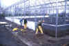
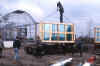
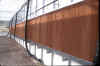
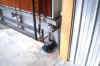
Greenhouse A glass-clad curved-roof greenhouse measuring 29.3 m (96 feet, East-West) by 25.6 m (84 feet) consisting of four East-West oriented and gutter-connected greenhouse bays was designed and constructed. Tempered glass (4 mm thick) was used in the roof and sidewalls for optimum light transmission. Each of the four East-facing end walls houses a 1.2 m (4 feet) diameter exhaust fan. Along the West wall, a 1.2 m (4 feet) high evaporative cooling pad was installed just inside a similarly sized ventilation window. Just below the gutters, 4.3 m (14 feet) above the greenhouse floor, a 50% transmittance shade curtain can be deployed to reduce solar radiation on the crop. Directly underneath the shade curtain, a supplemental lighting system is positioned with the bottom of the reflectors 3.2 m (10.5 feet) above the top of the canopy. A total of 144 luminares, each equipped with a 600-watt high-pressure sodium lamp, provides a uniform light intensity of 200 µmol-m-2-s-1 (1500 ft-cd) at canopy level. The greenhouse is heated with two natural gas fired hot water boilers (351 kW or 1.2 MBtu/hr input each). The hot water is circulated through radiant fin pipes located around the insulated greenhouse curtain wall (1 m or 3.3 feet high) and overhead in each greenhouse bay. Smooth heating pipes located near each greenhouse gutter are used to increase snowmelt and as a rail system for a transport platform. At the same height as the supplemental lighting system, rows of vertical airflow fans (a total of 44 over the growing area) were installed to increase air movement over the crop. The continuous air movement is necessary to increase plant transpiration and thereby reduce tipburn. Three of the four greenhouse bays contain a 25.6 m (84 feet) by 6.1 m (20 feet), PVC-lined pond supported by a 0.15 m (6 inches) thick concrete floor and 0.3 m (1 foot) high concrete retaining walls. The fourth bay contains a 25.6 m (84 feet) by 4.9 m (16 feet) pond and a sidewalk along the entire South wall of the greenhouse. A carbon dioxide enrichment system was installed to allow for an increase in the carbon dioxide concentration of the greenhouse air. Nutrient Solution Each pond is filled with approximately 25 cm (10 inches) of nutrient solution which is recirculated continuously utilizing a pump and a PVC pipe distribution system. In addition, each pond is equipped with a heating system to maintain the desired nutrient solution temperature of 24ºC (75ºF). Hot water from the greenhouse heating system is recirculated through a plumbing system submerged in the nutrient solution. The depth of the nutrient solution is controlled by a level sensor, which is connected to a solenoid valve. Municipal tap water is added to maintain the desired nutrient solution volume. Vaporized liquid oxygen is added to each nutrient solution volume in order to maintain a minimum required dissolved oxygen concentration of 4 mg/L. Four spargers (porous gas diffusers) release tiny oxygen bubbles into the nutrient solution as it is recirculated through each of the pond distribution systems. The composition of the nutrient solution in each pond (Electrical Conductivity and pH) is checked at regular intervals by a fertilizer injection system located in the adjacent headhouse. A plumbing system sequentially directs the recirculating nutrient solution from each pond to the headhouse where adjustments are made before the nutrient solution is returned to each pond. Pictures of the Floating
Hydroponics Greenhouse Design:
More Information
|
||||||||||||||||||||||||||||||||||||||||||
|
| ||||||||||||||||||||||||||||||||||||||||||