|
HEADHOUSE CONSTRUCTION 
|
|
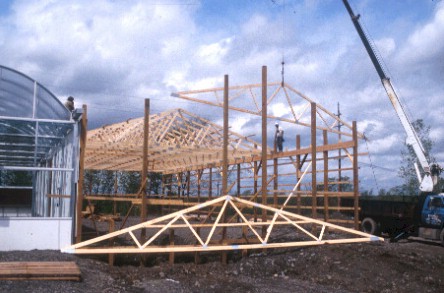
Installation of
wood trusses to support the roof of the headhouse. |
|
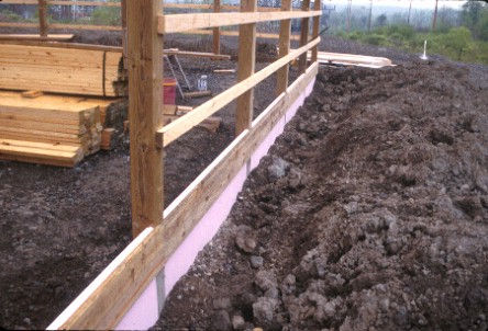
Two-inch thick
perimeter insulation (approximately 2 feet deep) is installed along the
outside walls of the headhouse. This perimeter insulation makes for an
effective heat-loss barrier.
|
|
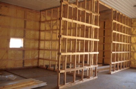
Framing of the
interior walls for the cold storage room located in the headhouse. Note
the yellow fiberglass insulation blankets in the outside walls and the
metal clad ceiling. Fiberglass insulation blankets were installed in the
attic, just above the metal ceiling panels.
|
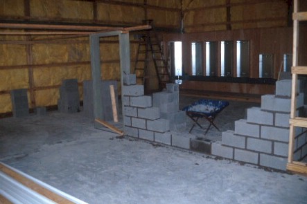 |
Inside the headhouse
(40 feet wide by 96 feet long), a utility room is constructed. Because the
boilers would be installed inside this room, the local building code
required this room to have a high fire rating. Therefore, the walls of the
utility room were constructed from concrete blocks.
|
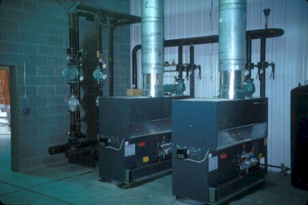 |
Two natural gas fired
hot-water boilers (1.2 MBtu/hr input each) were installed in the utility
room.
|
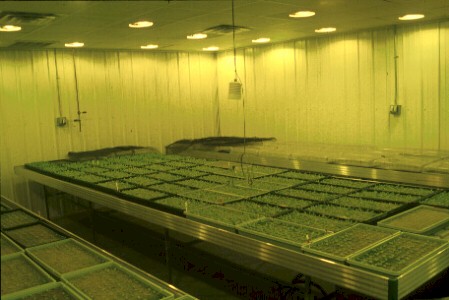 |
General view of the
plant growth room inside the headhouse. |
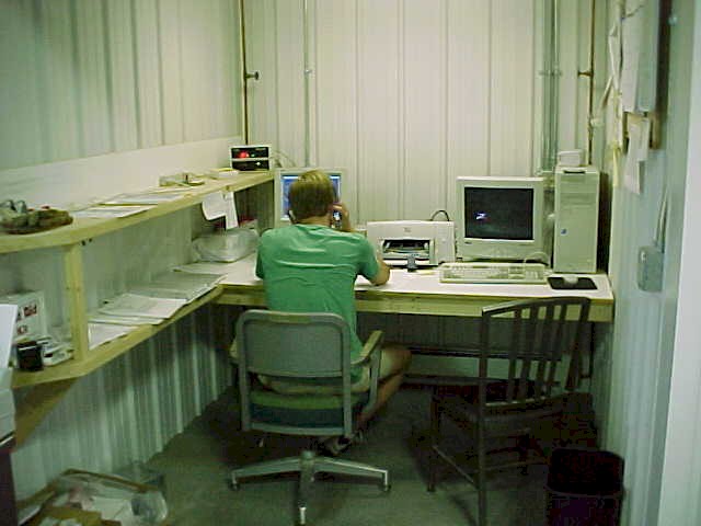 |
The office area with
the environment control computer system. |
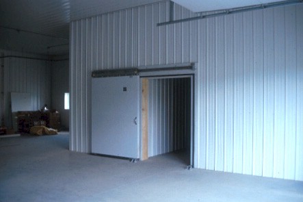 |
The finished cold
storage room, large enough to hold several days of harvested product. |
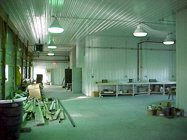 |
The main work area
inside the headhouse is under construction. The greenhouse is located to the
left of this picture. |
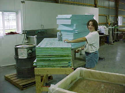 |
The washing station
inside the headhouse is used for cleaning the Styrofoam™ floaters. A weak
bleach solution is applied before the floaters are thoroughly rinsed.
|
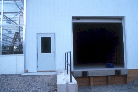 |
The main entrance
door to the facility (facing East) and, to its right, a loading dock with
overhead door. |
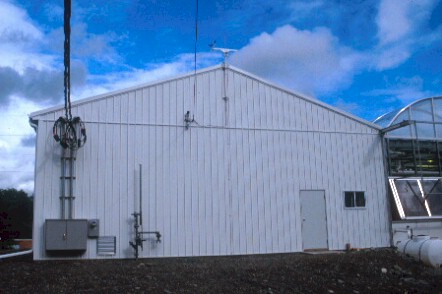 |
The utilities
(electric, gas, water, and phone) were brought into the building from the
West wall of the headhouse. Note the weather station (wind direction, wind
speed, outside temperature and humidity, and solar radiation) at the ridge
of the headhouse. |
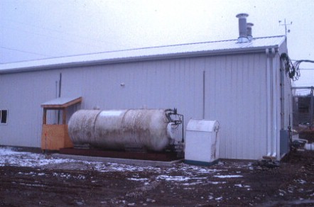 |
A (liquid) carbon
dioxide tank with refrigeration unit (to the right) is installed along the
North wall of the headhouse. The liquid carbon dioxide is vaporized before
it is directed to the greenhouse and growth room. Carbon dioxide enrichment
is used to increase crop growth. |
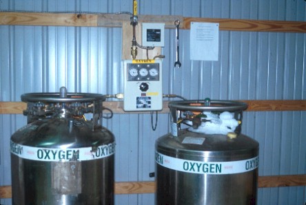 |
Liquid oxygen tanks
are supplying vaporized oxygen gas to the recirculation nutrient solutions
in each of the four ponds. An automatic switching valve (center) is needed
to switch from one tank to the other when the first tank runs empty.
|
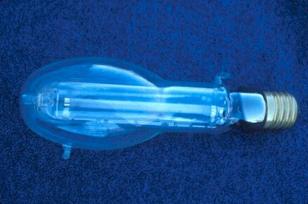 |
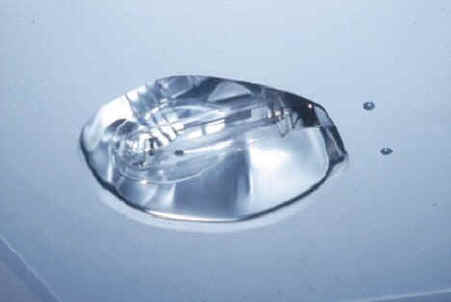
Custom-made,
water-cooled high-pressure sodium lamp bulb (600-watt). Water is pumped
through the outer glass envelope. The operating lamp heats the cooling water
as it passes through the bulb. Note the inlet and outlet ports to the sides
of the lamp bulb. |
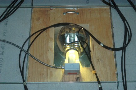 |
Top-view of the
installation of a water-cooled high-pressure sodium lamp and reflector
located in the growth room. The lamp and reflector are mounted in a two by
two feet ceiling panel, which is part of a so-called false ceiling. Note the
black hoses bringing cooling water to and from the lamps. The (heavy)
luminaire ballast is located several feet away from the lamps and is not
supported by the false ceiling. |
 |
Operating water
cooled lamp |
 |
Bottom-view of the
installation of a water-cooled high-pressure sodium lamp and reflector in
one of the ceiling panels located in the growth room.
|
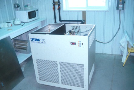 |
A recirculating
chiller removes heat from the cooling water and returns it to the
water-cooled high-pressure sodium lamps located in the growth room.
|
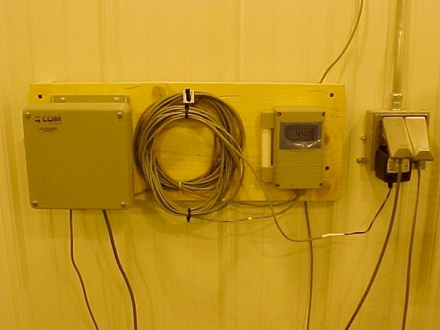 |
A carbon dioxide
sensor inside the growth room registers the carbon dioxide concentration.
The sensor communicates with the environment control system and the computer
operates a solenoid valve in the carbon dioxide supply line. A similar setup
is used in the greenhouse to control its carbon dioxide concentration.
|
|
Back
to FH Greenhouse |