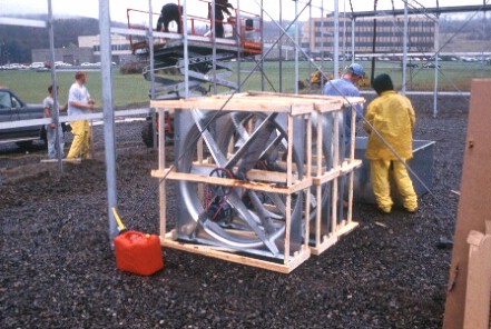
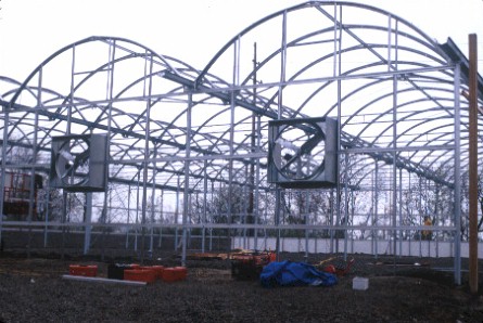
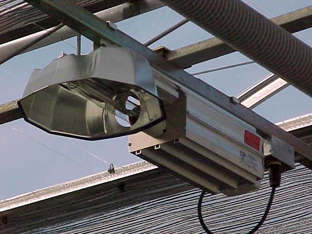
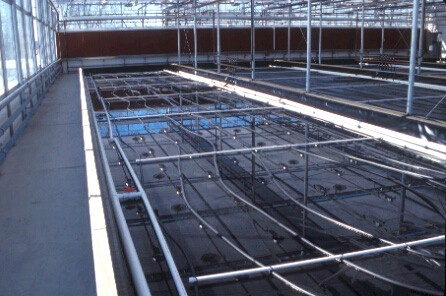
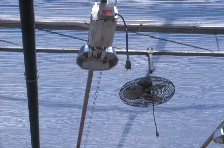
GREENHOUSE CONSTRUCTION


Before any construction could start at the building site, a building permit was secured from the local zoning and building code enforcement office. The permit was issued after the proposed building plan was discussed during an open hearing for the local town board. Members of the board voted on and approved the building plan.


Site preparation included leveling and landscaping of the building site. In addition, drainage ditches and a catch basis were installed to make sure rain water collection and runoff were handled properly.
A truck-mounted auger is used to drill holes for the greenhouse anchor posts.
The auger holes are filled with concrete before the anchor posts are inserted in the wet concrete.
An anchor post is inserted in wet concrete. Yellow strings are used to carefully mark the exact location of the center of each post.


The anchor posts are being inserted in holes filled with wet concrete. Once all the anchor posts are installed and the concrete dried, the site is leveled again and layer of gravel is applied on top.
The greenhouse construction company shipped the many construction components to the building site. A forklift is used to unload the bigger pieces.
Close-up of the connection between a greenhouse post and its trusses. Note the gutter support on top of the post and the top of an anchor post just sticking out of the gravel.
The greenhouse posts and connecting trusses are positioned on the ground. Several people are needed to lift a row of posts and trusses and secure the greenhouse posts to the anchor posts.
A movable and adjustable work platform comes in very handy when installing gutter segments between the posts.
The roof arches are installed. Each row of arches constitutes a greenhouse bay. Four bays (measuring 21 feet wide by 96 feet long) are needed to cover the entire greenhouse. The ridge of each greenhouse bay is oriented in the East-West direction.
In order to secure the glass panels to the roof arches, special aluminum profiles are attached the top of the roof arches.


Each greenhouse bay will be equipped with a four feet diameter ventilation fan.
A four feet diameter ventilation fan is installed in the East wall of each greenhouse bay.
So-called curtain walls (four feet high) are installed around the outside perimeter wall of the greenhouse. The bottom foot of the walls is dug into the ground to make for an effective heat-loss barrier.
Drain lines are installed inside the greenhouse to allow for the collection of wastewater.
Once the greenhouse framing structure was completed, crates with tempered safety glass (0.17 inch thick) were delivered to the construction site. Each pane of roof glass measured 6 by 12 feet.
The crates with glass are opened and unloaded onto a lifting frame.
The frame with several panes of glass is lifted and placed on a rolling structure, which rolls along the greenhouse gutters.
One by one, the panes of glass are secured to the roof of the greenhouse. Each pane is secured at the ridge first, and at the gutter last. Rubber strips are inserted between the glass and the greenhouse frame. 


The curvature of the glass is possible due to the fact that the glass is tempered. This curvature adds additional strength to the roof construction.
The ventilation inlet window is located along the entire West wall of the greenhouse. The external frame is needed to support the opening and closing mechanism of the window.


Shade curtains are installed to be able to reduce the amount of solar radiation reaching the plants during the brighter summer months. The curtain also acts as an energy shield when it is closed during the night in order to prevent warm air from rising and cooling against the cold glass roof.


 High-pressure sodium luminaires (with 600-watt lamp bulbs) are installed in the greenhouse. A total of 144 luminaires is installed over the total growing area of 6640 square feet (one lamp for every 46 square feet). The distance between the top of the plant canopy and the bottom of the luminaires is 10.5 feet.
Vertical airflow fans are installed to blow greenhouse air directly onto the lettuce crop. This air movement is needed to help prevent tipburn (a physiological disorder in lettuce plants, comparable to blossom end rot affecting tomato). The extra air movement increases plant transpiration, resulting in increased uptake of water and nutrients (including Calcium, which plays a major role in the occurrence of tipburn).
An evaporative cooling pad was installed along the entire ventilation inlet opening in the West wall of the greenhouse. On warm days, the pad is wetted and the incoming air is cooled as it passes through the pad and water evaporates into the incoming air.


A pump and plumbing system is installed to pump water from and (outside) storage tank onto the evaporative cooling pad. The excess water is drained and returned to the storage tank.
A storage tank for the evaporative cooling water is installed just outside the greenhouse. This tank will only be used during the warmer summer months and is drained and cleaned before the winter season.
A reinforcing wire mesh is installed on the greenhouse gravel floor just before the concrete is poured.
Motorized wheelbarrows are use to transport concrete from the concrete truck to the appropriate destination inside the greenhouse.
A crew of workers is spreading and leveling the fresh concrete inside the greenhouse. The reinforcing wire mesh is carefully lifted into the bottom half of the concrete floor for maximum effectiveness.
After the concrete has hardened for a few hours, a power screet is used to smooth the top layer of the floor and to make sure water drains properly to the various wastewater drains.
The concrete greenhouse floor is hardening off.


The greenhouse heating contractor is installing overhead heating pipes. The heating pipes are welded together inside the greenhouse.
Small, reinforced retaining walls (8 inches wide by 13 inches high) are build out of concrete. These walls are used to contain the nutrient solution in each of the four ponds.
A PVC liner (30 mils) is installed in each pond to prevent the nutrient solution from leaking away. Note the walkway along the entire South wall of the greenhouse.
Each pond is equipped with a nutrient solution recirculation system (larger white PVC pipes) and heating system (smaller black plastic pipes looped on the bottom of the pond).
The local electric utility company is working on the installation of a new (800 amp) service for the greenhouse operation.


The local utility company is installing a gas line to the greenhouse site.


Back to FH Greenhouse