|
OPEN-ROOF GREENHOUSE PROJECT PICTURES
Construction 1-10 11-20 21-30 31-40 41-50 Crop Production 51-60 |
|
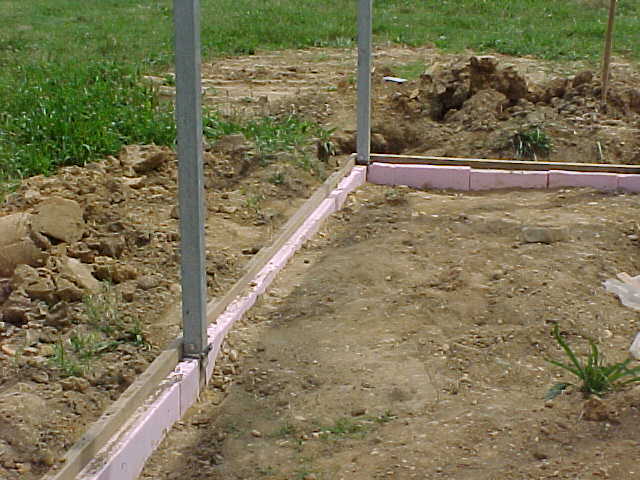 |
Two feet deep perimeter insulation (two inches thick) is installed to reduce the heat loss through the greenhouse floor. |
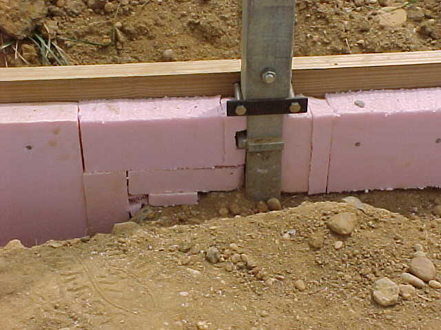 |
Perimeter insulation (two inches thick) is carefully installed around the concrete footings of the greenhouse posts. The insulation will help reduce the heat loss through the greenhouse floor. |
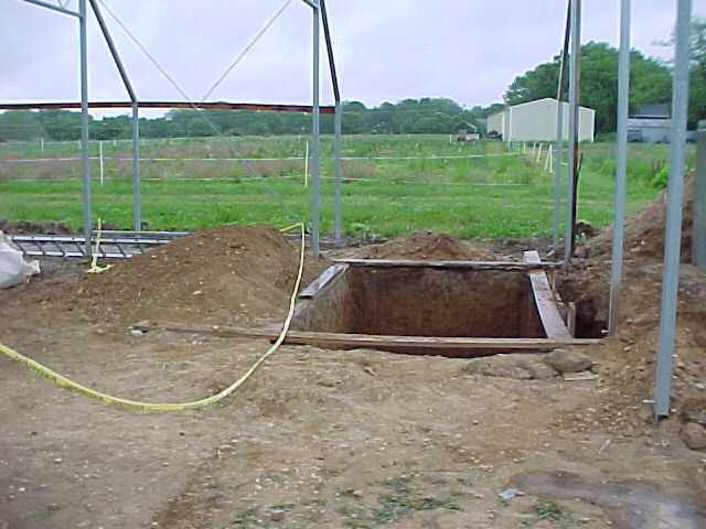 |
Holes are dug for the below-ground irrigation tanks. These pre-fabricated tanks will serve as storage tanks for the recirculating nutrient solution. The ebb and flood irrigation floor is divided in two sections and each section has its own storage tank. |
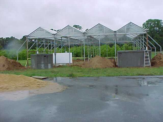 |
The pre-fabricated concrete storage tanks are ready to be installed in holes dug underneath the future greenhouse side walk. Two tanks are needed for the two separate sections of the ebb and flood irrigation floor. |
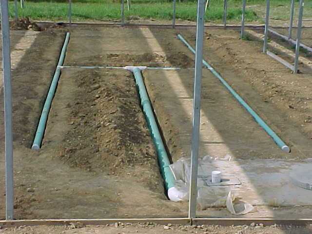 |
A distribution plumbing system is installed, which will allow the nutrient solution to be pumped onto and drained from the ebb and flood irrigation floor. The pipes will be located directly underneath the four inches thick concrete floor. In the foreground, the plastic-covered top of one of the nutrient solution storage tanks is visible. |
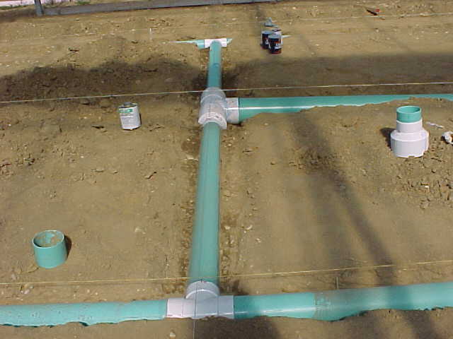 |
Detailed view of the distribution plumbing system, which will allow the nutrient solution to be pumped onto and drained from the ebb and flood irrigation floor. |
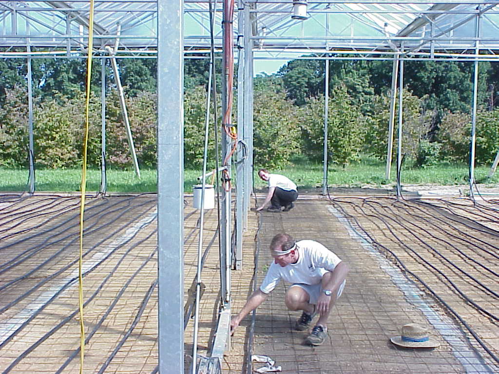 |
Polypropylene heating pipes are attached to the concrete reinforcing wire prior to pouring the concrete floor. Each heating line loops from end-to-end three times for a total length of 360 feet and is attached to a header system. The floor heating system will provide a very uniform heat distribution over the entire floor area. The root system of the potted plants grow directly on the floor will benefit from their close proximity to this evenly distributed heat. |
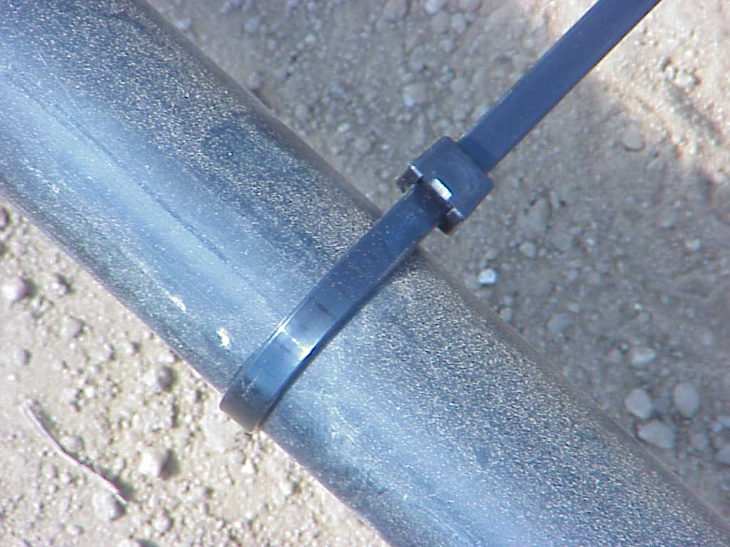 |
The polypropylene heating pipes are attached to the concrete reinforcing wire prior to pouring the concrete floor. This kept the heating lines firmly in place during the placement of the concrete. |
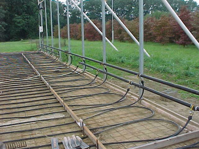 |
The polypropylene heating lines are in place and attached to a header system. The heating lines were pressurized with water during the concrete placement to add weight and to make sure no leaks developed during the installation process. |
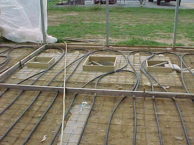 |
The polypropylene heating lines are positioned around the access holes to the underground nutrient solution storage tanks. |